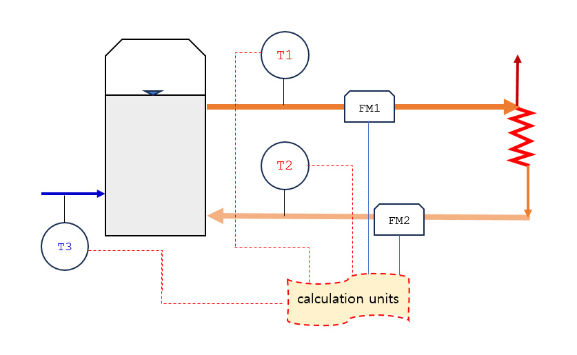
The system is used for measuring the energy production rate in the heat source that produces and supplies district heating. It is installed in the discharge pipeline of the heat source and consists of two flow measurement points and three temperature measurement points. The system is composed of flow measurement units, temperature measurement units, and calculation units. This product, which is currently made, is developed to achieve optimal performance by specializing in Uzbekistan's use environment.
Since heat water is supplied by conventional boiler methods, the supply system is operated in various ways for heating and hot water usage. In practice, because the heat water is consumed in the middle, the supply flow rate and the return flow rate do not match. Therefore, flow meters need to be installed in both the inlet and outlet pipelines. Additionally, since extra water is supplied to compensate for the consumed flow, temperature measurements must be taken for supply, return, and supplementary water temperatures simultaneously.
Here, "M" refers to volumetric flow rate.
In South Korea: There are differences in the thermal capacity coefficient depending on whether the flow measurement unit is installed on the supply line (typically by SK E&S) or the return line (typically by Korea District Heating Corporation).
In Uzbekistan: The method of supplying flow differs between winter and summer. During summer, when the supply line may be shut down for maintenance, the system is designed to handle two types of operation modes. The flow and thermal quantity measurement system automatically recognizes and adjusts to the operation mode by reflecting the flow direction (±) and temperature values, allowing for accurate calculation and accumulation of thermal energy based on the operation mode. (Ongoing improvements in installation.)
| Mode | Piping Structure | Heat Calculation Method |
|---|---|---|
| KDHC (Return) |
 |
Q = K *M supply * (T1 – T2) Supply : Forward direction K : Supply Heat conversion factor |
| SK (Supply) |
 |
Q = K *M return * (T1 – T2) Return : Forward direction K : Return Heat conversion factor |
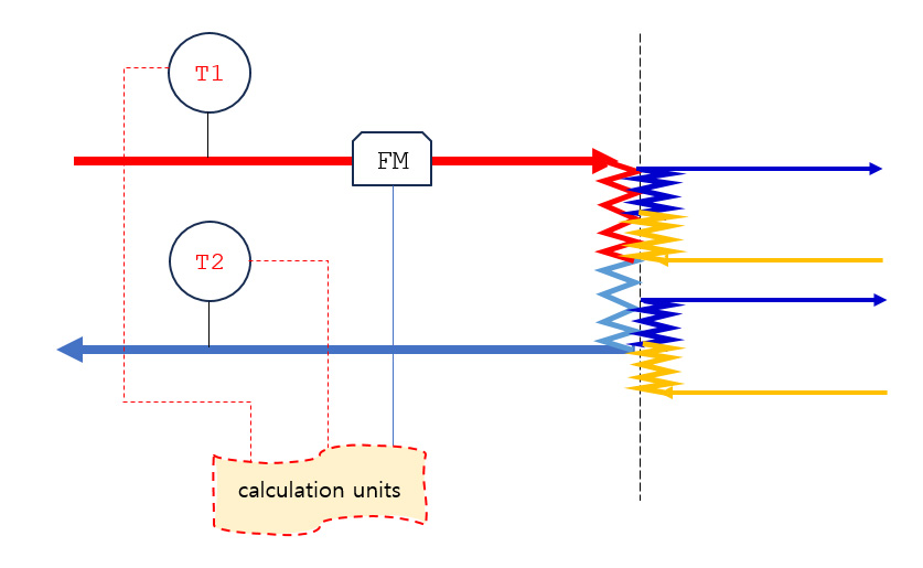
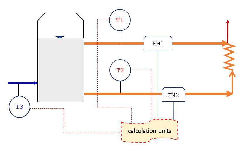
| UZ1 (Winter) |
 |
Q = M supply * (T1 – T3) – M return * (T2 – T3) Supply : Forward direction Return : Forward direction |
| UZ2 (Summer1) |
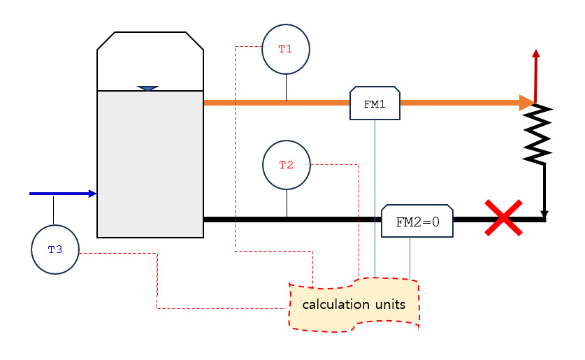 |
Q = M supply * (T1 – T3) Supply : Forward direction Return : Not used |
| UZ3 (Summer2) |
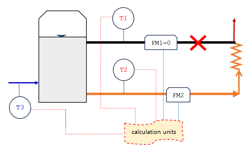 |
Q = M return * (T2 – T3) Supply : Not used Return : Reverse direction |
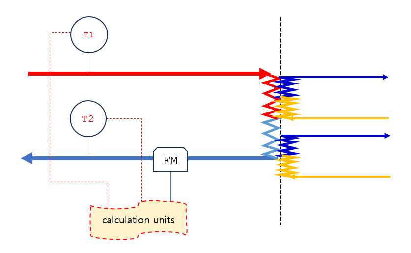
| UZ4 (Summer3) |
 |
Q = M supply * (T1 – T3) + M return * (T2 – T3) Supply : Forward direction Return : Reverse direction |
The velocity distribution of the fluid in the pipeline fluctuates in real-time due to the installation position and pipe structure. To obtain stable flow velocity values despite various changes, the unit is designed with a three-path cross-sectional arrangement.
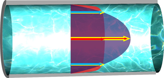
[Figure 1] Velocity Distribution in the Pipeline (Laminar and Turbulent Flow)
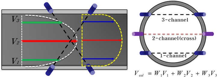
[Figure 2] Arrangement of the Three-Path Ultrasonic Measurement Lines and Flow Velocity Calculation
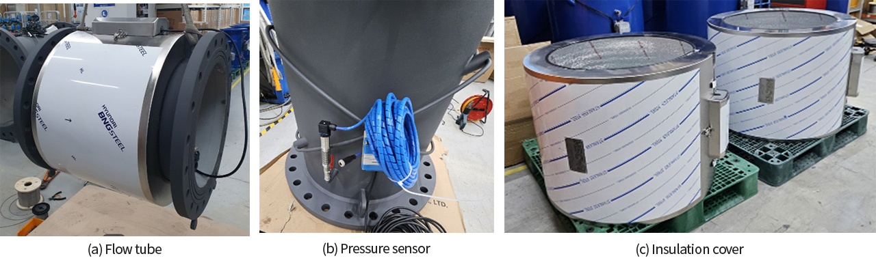
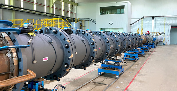
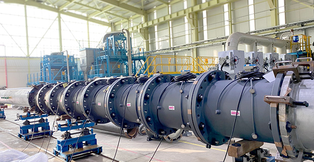
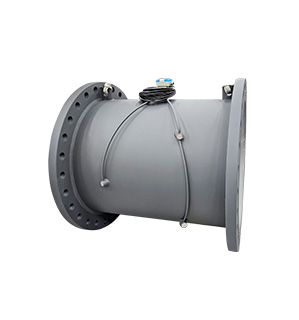
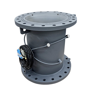
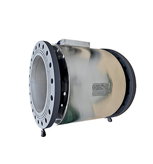
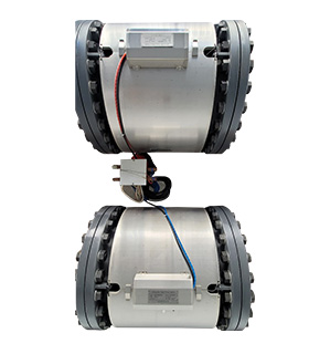
[Figure 3] High-Temperature Ultrasonic Flow/Heat Meter System
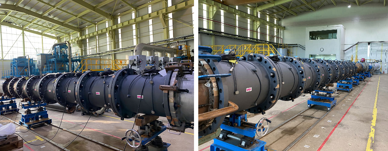
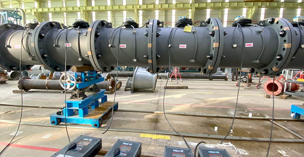
[Figure 4] Performance Evaluation in Progress
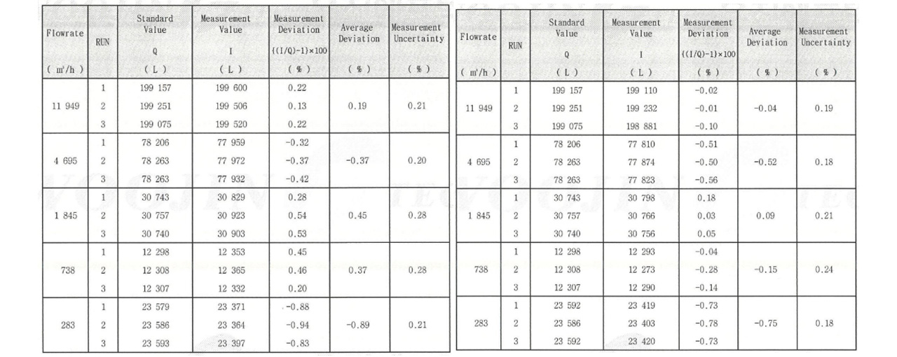
[Figure 5] Performance Evaluation Results (@KOLAS)
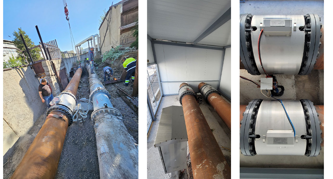
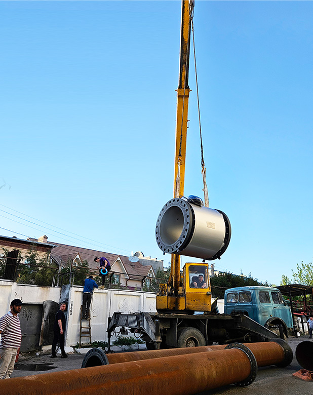
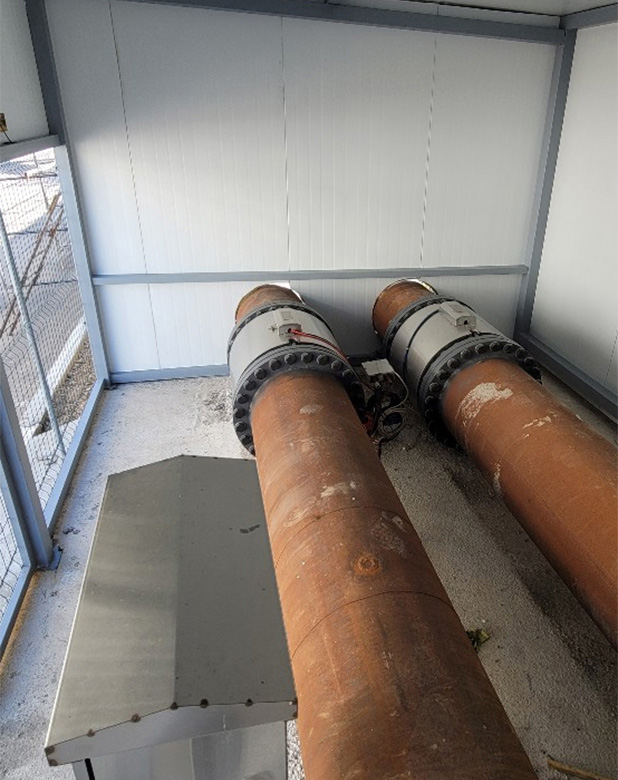
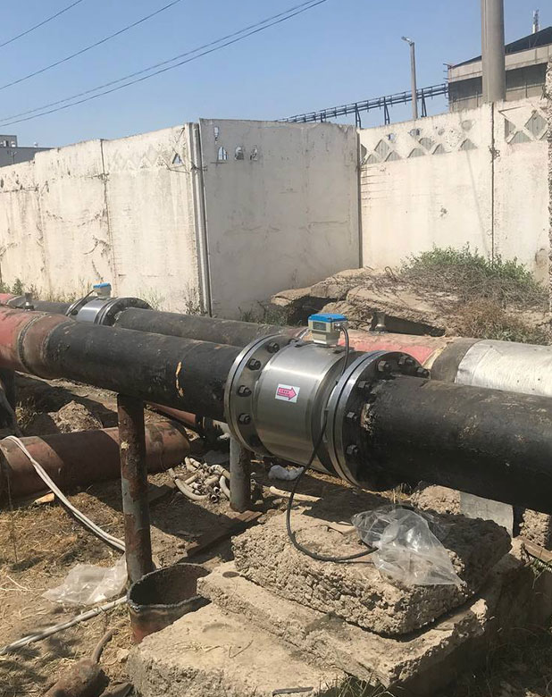
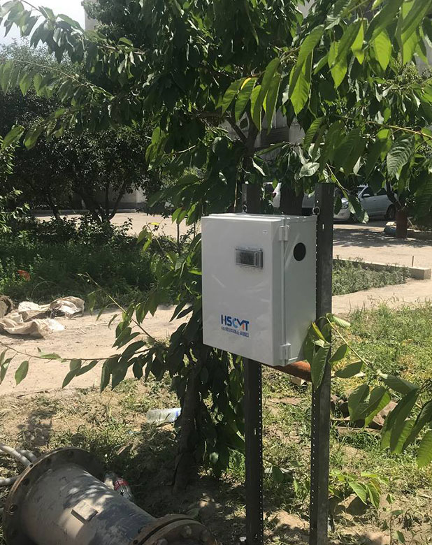
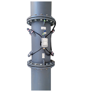
[Figure 6] On-Site Installation Example (@Tashkent)
⋅ Model: UR-1100(Ultrasonic Heat•Flow Meter)
⋅ DN(㎜): (300) 500A ~ 1000A
⋅ Specification
| DN(mm) | 500 | 600 | 700 | 800 | 900 | 1000 |
|---|---|---|---|---|---|---|
| PN | 16 (1.6 Mpa) | |||||
| Interplanar Distance(L) | 740 | 840 | 940 | 1050 | 1150 | 1260 |
| Bolt Standard | M30 | M33 | M33 | M36 | M36 | M42 |
| Number of Bolts(EA) | 20 x 2 | 24 x 2 | 24 x 2 | 24 x 2 | 28 x 2 | 28 x 2 |
| Overload Flow Rater Qs (㎥/h) |
7100 | 10200 | 13900 | 18100 | 23000 | 28300 |
| Maximum Flow Rater (Qp (㎥/h)) |
3550 | 5100 | 6950 | 9050 | 11500 | 14150 |
| Minimum Flow Rater (Qi (㎥/h)) |
71 | 102 | 139 | 181 | 230 | 283 |
| Starting Flow Rater (㎥/h) |
0.03 | 0.03 | 0.1 | 0.15 | 0.2 | 0.25 |
| Flow Ratio (Qp / Qi) |
50 | |||||
| Flow Accuracy | ±1% MV | |||||
| Channel | 3 | |||||
| Max. Flow reading (㎥) | 99999999(8-Digt.) | |||||
| Max. Heat reading (Gcal) | 99999999(8-Digt.) | |||||
| Temperature range | 0 ~ 130 ℃ | |||||
| Temperature difference range | 3 ~ 80 K | |||||
| Temperature sensor | PT 500 (3 Wire) - Supply, Return, Cold | |||||
| Pressure range | 0 ~ 0.2 Mpa (FS 0.25%) - Supply, Return | |||||
| Communication Interface | RS-485(Modbus-RTU) | |||||
| Power | AC220V | |||||
| Flange Std. | JIS 16K | |||||
⋅ Flow Tube Material: STS-304, SS275(flange carbon steel)
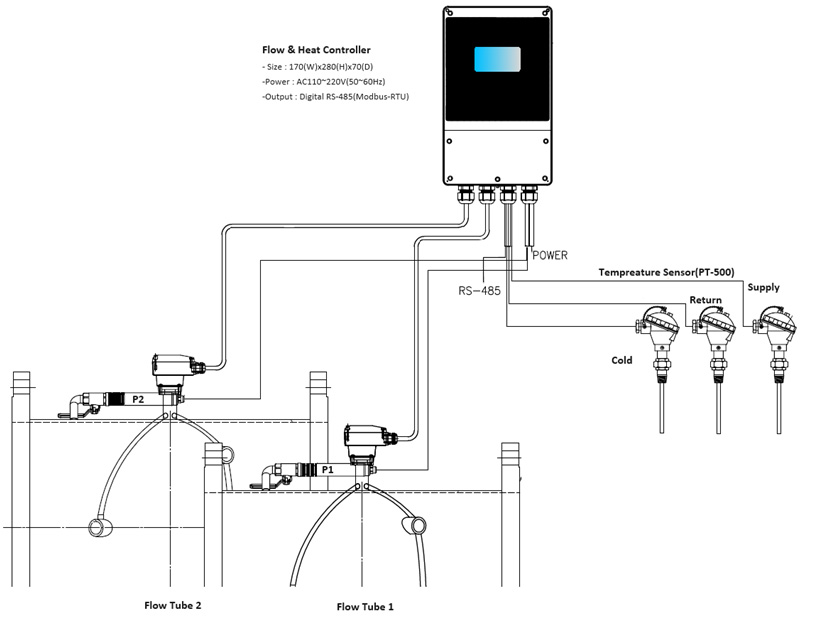
[Figure 7] Overall System Configuration Diagram
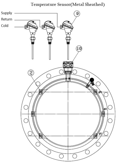
[Figure 8] Temperature Measurement Unit Configuration